Installation procedure for new A06B-6044, A20B-1000-069X, and A20B-0009-053X spindle drive PCB.
Step 1
Set the jumpers to match your old spindle PCB.
Step 2
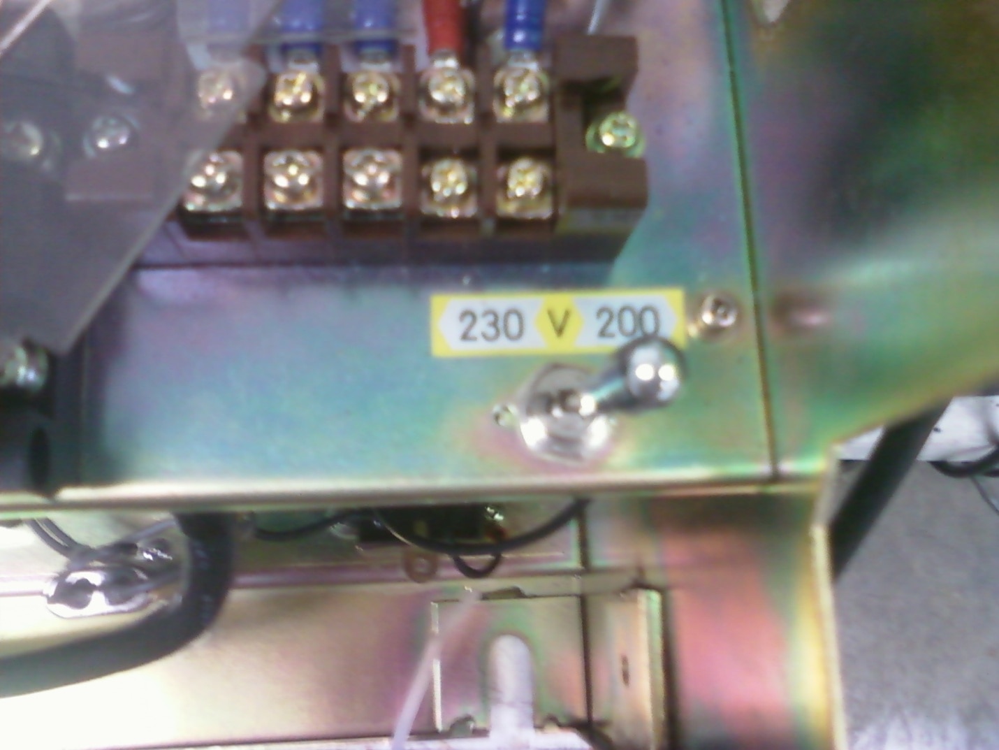
Set the 200/230 voltage switch in the drive cage to match the setting on the old drive. The switch is under the lid on the smaller spindle drive cages. Not all spindle drives have this switch.
Step 3
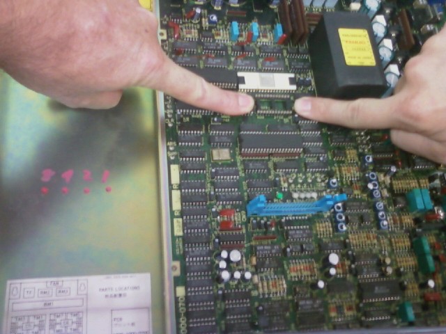
Move the software chip from the old spindle PCB to the new spindle PCB. Failure to move the software chip from the old drive to the new drive will generate an Alarm 14. LEDs #8, #4 and #2 will be red.
Please note: The chip has a notch or key on it, and so does the socket the chips go into. Please match the notch or key on the chip with the notch or key on the socket
Step 4
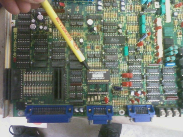
Move DAC chip, if used, from the old spindle PCB to the new spindle PCB.
The DAC chip is an option chip. If the DAC chip is present on the old spindle PCB, it must be moved to the new spindle PCB and put into the same socket that was used on the old spindle PCB. Failure to move this chip can cause the spindle to rotate very slowly in automatic operation.
Get your Fanuc CNC machine back up and running.
TIE offers same day shipping on more than 100,000 Fanuc CNC parts in stock. We offer a 1 year in service warranty on all parts and repairs.
Shop PartsWas this helpful?
0 / 0